Beginner's Guide to STM32CubeMX
STM32 CubeMx tutorial
Introduction
Welcome to this STM32 Cube Mx tutorial. You might be wondering what
is it all about? Don’t worry you will find the answers here. STM32
Cube Mx is a free software provided by ST Microelectronics who builds
the STM32 line of micro controllers. One issue with these devices is
that a lot of code needs to be written to initialize the device.
The STM32 Cube Mx is a GUI that makes life much easier. It helps
reduce the burden regarding initializing the micro controller. Bear
in mind though that it will not write the code regarding the
operation you want to make. Lets take an example, suppose I want to
use a STM32F100VGT6 and blink an external LED. The STM32 Cube Mx will
help me get the micro controller setup and get an output port ready
for me. Unfortunately it will not tell the micro controller that I
want to blink the led and at what speed I want the LED to blink. I
have however given a small glimpse on how to turn switch on an output
port at the end of this article.
So how do you get started with this software? Just follow the steps
below.
Create an account on ST
First of all you need to go to http://www.st.com.
Register for an account with your email address. Without a registered
account you cannot dowload any content fom ST. Before going further
you need to know that the STM32 Cube comes in two parts:
1) STM32FXXX firmware
2) STM32 Cube Mx application.
Download STM32FXXX firmware
Once
registered you need to download a first software which is called the
firmware.
The STM32 firmware is what now replaces the standard peripheral library. You must use this firmware as this is the only one that STM32 Cube Mx recognizes. The implementation of the firmware is completely different from the standard peripheral library and code is written differently.
The STM32 firmware is what now replaces the standard peripheral library. You must use this firmware as this is the only one that STM32 Cube Mx recognizes. The implementation of the firmware is completely different from the standard peripheral library and code is written differently.
The
firmware is also very specific to the STM32 line you are using. If
you are using an STM32F103RBT6 for instance, you will need to
download the STM32F1XX firmware. Now if you will use several micro
controllers, I would advise to download all relevant firmware based
on the STM32 models you will be using.
Once
downloaded, install the firmware(s) to a folder and note its(their)
location. Do not mix all firmware(if you are using several) in a
single folder keep them separate.
Downloading and installing STM32CubeMX
Once you have obtained your firmware(s) next you need to download and
install STM32 Cube Mx using your ST account.
Launching STM32 Cube
Once the STM32 firmware(s) and the STM32 Cube Mx is installed, launch
the software by clicking on the icon below on your start menu. Note
that this is the current icon at time of writing and it might change
afterwards.

Startup screen and new project
When
the STM32 Cube Mx Launches you will get the screen below. You will
need to click on New
project to
begin.

Option1: Selecting your micro controller(ic’s or custom
boards)
Next
you need to use the type your micro controller model number in the
Part Number
Search in
the top left corner. Enter the full model number, this will make the
search more accurate. Once your micro controller is found, select it.
Here I am using the STM32F100RB and I will continue with this micro
controller till the end of this article.

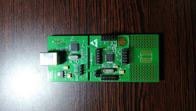
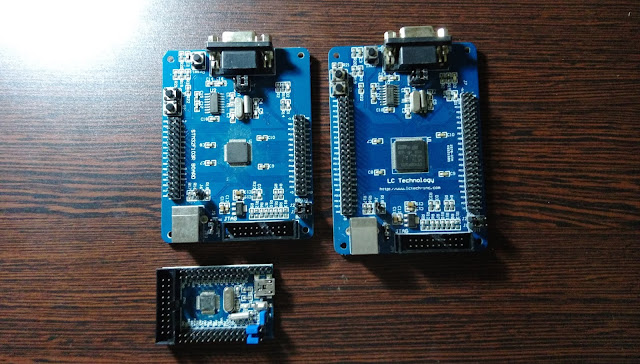
Option2: Selecting your
board(for manufacturer development boards)
In
case you are writing code on a specific development board this is the
way to go. For example, below I wanted to go for the STM32 Value line
board. The advantage of choosing the board is that STM32 Cube Mx
knows how the micro controller and the devices on the board are
connected together.

IO
Configuration
The
next step involves defining which ic pins will do what functions.
Bear in mind that certain pins are reserved for certain functions.
You can make these pins behave as an input/output port or perform
their special function only but not both. An example of such a pin is
the ADC1 port. You will also notice that some pins are painted
yellow, such as VDD, VSS, VSSA below. These are power pins and cannot
perform any other function. The pins which are gray have not been
configured. To configure a pin click on it to select. The left menu
will adjust accordingly. If you want to configure by function, then
use the left menu directly.

Configuring for external clock
Lets start configuring one of the most important pins, the external
oscillator pins. The reason why I am doing this step is that I want
the IC to use an external oscillator. Since this is a functionality,
I will go to the left menu and expand RCC. Next
I get three options, I will set the following options:
Settings
|
Value
|
Reason
|
High Speed Clock (HSE)
|
Crystal/Ceramic resonator
|
This is the type of oscillator which is on my
board
|
Low Speed Clock (LSE)
|
Disabled
|
This is normally for 32KHz oscillators which I
don’t intend to use
|
Master Clock Output
|
Unchecked
|
This feature outputs the HSE pulses, I don’t
require this feature
|

Once these settings have been defined, the RCC_OSC_IN
and the RCC_OSC_OUT
will end up becoming green as shown above. The green color is an
indication of a configured pin.
Set debugging options
The debug pins need to be set
next. These pins are important as they will allow the onboard or and
external programmer to write the program that has been written inside
the microcontroller. Since this is a built in function the same
procedure are for Configuring for external clock
has
been used below.
Settings
|
Value
|
Reason
|
Debug
|
Serial wire
|
I want the microcontroller and the programmer
to use serial wire and not JTAG
|
System Wake-Up
|
Unchecked
|
This feature is not required
|
Timebase source
|
Systick
|
This is the default value
|

Clock configuration tab
Next we need to define the speed at which we want the microcontroller
to operate. In order to do so click on the Clock Configuration
tab
at the top left next to the Pinout tab.
Since I want to use the external oscillator on my board I need to
select HSE
but the one circled in red in the diagram. If you follow its track
back to the left, the symbols indicate an external oscillator. Next
the PLLMul
has
been set to X3. The reason behind is that I have an 8MHz external
oscillator on my board and my microcontroller can operate at a
maximum speed or 24MHz so 3 x 8MHz=24MHz.

Setting IO Pins
To
set IO pins, we will go back to the Pinout
tab.
Next
a right click needs to be done on the pin. In my case I want to set
port PC8 as an output pin. In that case the GPIO_Output
option
needs to be selected. The other options displayed are specific to
what functions this pin can perform. I have for the purpose of this
post chosen to do this in code and the example is provided at the
end. None of the less, setting the IO pin as shown will perform
similarly.

Configuration tab
The configuration tab
is the one next to the Clock Configuration tab.
The purpose of this tab is to give a summary of all the functions
that have been switched on in the microcontroller. Since the bare
minimum has been done this is why most boxes below are empty. Some
functions though not activated explicitly will still be displayed
such as DMA and
NVIC as
shown below. The analog box
for instead would have filled up if the ADC had been set up.

Power Consumption Calculator
Tab

Once
all the required functions have been ticked a graph of power
consumption will be displayed as per below. Please note that in our
case the graph is flat as we are not doing anything fancy but with
certain funtions swithced on power fluctuations could be observed.
Again a note of warning here of simulation v/s actual final circuit
needs to be taken into consideration.

Project Settings
The project menu contains a Settings
option that can be used to configure parameters for the current
project.

Once the project settings is chosen, the screen below will be
displayed. The sections in this screen are explained below:
Settings
|
Description
|
Project Name
|
Name of the current project
|
Project Location
|
Path of the current project
|
Toolchain Folder location
|
The folder into which all generated code will
be placed
|
Toolchain/IDE
|
The target software for which code needs to be
generated
|
MCU Reference
|
The microcontroller model for which code needs
to be generated
|
Use Default firmware location
|
Reference is made here more to the path below
this option. The path shown is where the STM32FXX firmware is
stored. The default path was not used in this example
|

Generating code
The
finals step once everything is complete is to generate the final
configuration code. Click on Project
and then on Generate
code.

A Progress bar will indicate progress of configuration code
generation.

Once the configuration code has been completed, a prompt will be
displayed proposing the options shown below.

Loading the code into the IDE
If the Open Folder
option is chosen the files shown below will be displayed. To load the
configuration code in the Ide, which is EWARM in this current
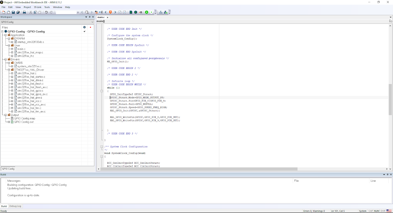
example, double click on the Project icon.

The project will load as per below. All the files in the left are
those which are required to make our microcontroller ready for the
functions that have been chosen. In this current example switching
Leds on ports PC8 and PC9.
Checking board schematic
Before the code is written a quick check on the board schematic is
required. The leds are connected to port PC8 and PC9 as mentioned
previously. The board schematic also indicates that the port needs to
be switched high to light up the leds.

Adding Code to Switch on Leds
Below is a short sample code that does three things
1) The highlighted code that says __HAL_RCC_GPIOC_CLK_ENABLE();
is initializing the PORTC clock. If the PORTC clock is not
enabled PORTC does not work. This code is present

2) Next comes the section in red below. In a few words these lines of
code are setting up PORTC where pins 8 and 9 will be outputs and no
internal pull ups will be required.

3) The final section in brown above gives the instruction to set
PORTC pin8 to high and same for PORTC pin 9.
Conclusion
I hope that this short article has given to you an idea of how the
STM32 cube MX works. Its a bit intimidating at first but once you get
used to it you’ll love the software for the time it saves you. I
can say by experience that the initialization process has been much
more simplified than with the Standard Peripheral Library. Bear in
mind though that with the new STM32 Cube library all codes are
completely different and you will need to relearn all of these.
Comments
Post a Comment